Choosing the right Camera Module starts with the image you need, not the highest megapixel number. A doorbell camera must capture faces in dim light. A drone needs low weight, fast focus, and stable video. A factory inspection camera may need precise color and repeatable detail. Different jobs demand different trade-offs.
The market reflects this variety. CIPA reported 8.49 million digital camera shipments worldwide in 2024, up from 7.71 million in 2023. Those figures describe cameras, not standalone modules, but they show sustained demand for imaging devices. Industry analysis from Yole Group also tracks continuing innovation in CMOS image sensors, including smaller pixels and advanced stacked designs. For buyers, the lesson is practical: sensor size, lens quality, and image processing matter together. Specs can mislead. A larger sensor may improve low-light performance, but it can also increase module size, power use, and cost.
Dr. Eric Fossum, a pioneer of CMOS active-pixel sensors, helped establish the technology behind many modern camera systems. His research offers a useful reminder: sensor architecture should serve the application. Start with field of view, working distance, lighting, resolution, and frame rate. Then check interface compatibility, operating temperature, and available software support. Ask for sample images under your real conditions. A datasheet cannot show every flaw. Lens distortion, motion blur, or color shifts may only appear in testing. That part is easy to overlook. The right module is rarely the one with the longest feature list; it is the one that performs reliably where you will actually use it.
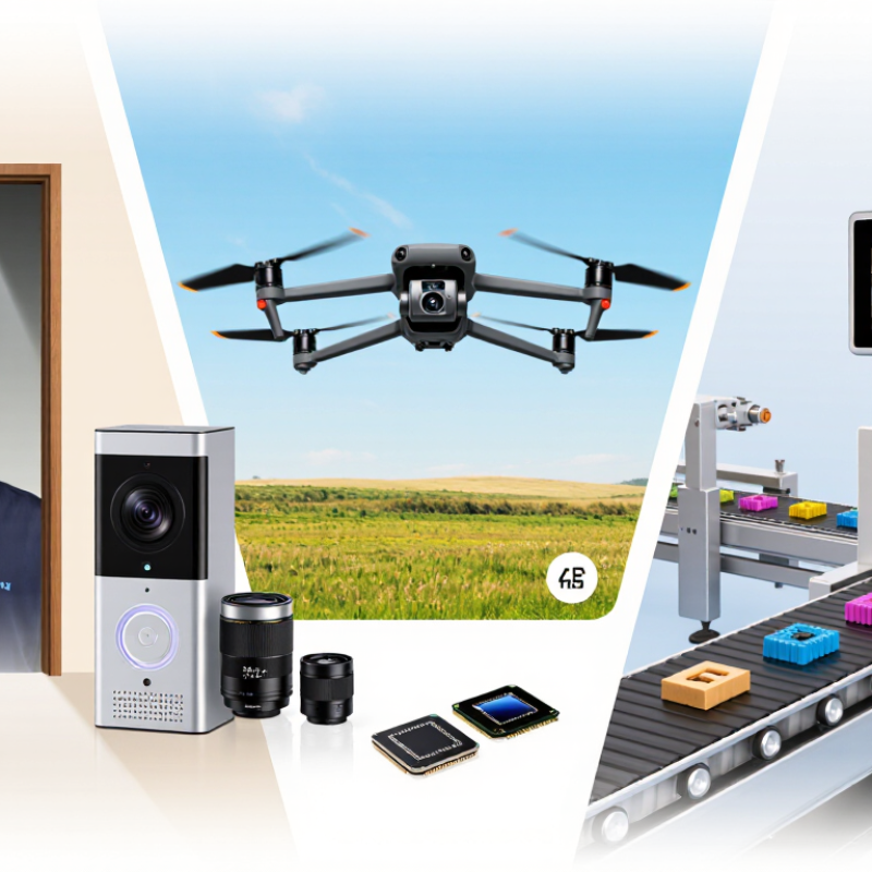
Before comparing camera modules, describe what the camera must see and where it will operate. A warehouse barcode reader needs sharp detail at close range, while a roadside monitor may need a wider view. Measure subject distance, motion speed, available light, and required image size. Be specific. “Good image quality” is not a requirement; it hides trade-offs between resolution, frame rate, and file size.
Check operating conditions at the actual installation point, not only in a lab. Record minimum and maximum temperatures, humidity, vibration, dust, and whether the camera faces direct sunlight. A module inside a sealed enclosure may heat up more than expected, especially during continuous recording. That detail matters. Confirm the lens field of view, focus range, and interface compatibility with the processor and cable length. A quick bench test can reveal focus drift or rolling-shutter distortion when objects move.
Plan how images will be used: inspection, measurement, identification, or general monitoring each favors different sensor characteristics. If color is essential, test under real lighting; fluorescent flicker can alter results. For low light, compare exposure time and noise rather than relying on resolution alone. Leave room for uncertainty. Early estimates are often wrong, so document borderline conditions and test them before finalizing the module.
Sensor size affects how much light a camera module can collect. A larger sensor often handles dim scenes with less visible noise, especially when the subject moves. It may also require more space and a suitable lens. That matters.
Resolution tells you how many image details the module can record. More pixels can help when cropping or reading small text, but they do not guarantee a sharper image. A soft lens or noisy image can waste those extra pixels. For a compact device, moderate resolution may produce cleaner results and smaller files.
Low-light performance depends on more than sensor size. Pixel design, exposure time, lens aperture, and image processing all play a role. In a dim hallway, a longer exposure may brighten the image but blur a moving person. Compare sample images captured at the same brightness, distance, and exposure settings. Look closely at dark corners, skin tones, and fine textures. Test it yourself. Published specifications are useful, but they rarely show how a module behaves in your actual enclosure. A small sensor may still be the right choice when space is tight and lighting is controlled. I would not choose by pixel count alone.
A camera’s lens determines how much of a scene fits into the image. Field of view (FOV) describes that coverage, usually across the horizontal, vertical, or diagonal frame. Match it to the subject and camera position. A narrow FOV can keep a distant object prominent, while a wider FOV can capture a whole room or work area. Wide is not always better. At close range, it may stretch objects near the edges and make straight lines appear curved.
Start with the scene’s width and the distance from the camera to the subject. Then check the lens specifications and sensor size, since both affect the resulting FOV. For example, a camera mounted above a small sorting table may need enough horizontal coverage to include the table’s far corners without making items too small to inspect. Leave a little margin for movement or installation changes. Measure twice. If possible, test the camera at its intended height and distance, using real lighting and representative objects. A paper calculation can estimate coverage, but it cannot reveal every reflection, edge distortion, or focus issue. I have found that the “right” view sometimes looks less dramatic than expected; that can be a good sign when useful detail matters more than scenery.
Start with the interface your system can actually support. Check whether the camera module uses USB, MIPI CSI-2, or another connection, and confirm your processor and cable match it. A connector that fits is not proof of compatibility. Compare pinouts, data rates, and available drivers before ordering. A mismatch can turn a promising prototype into a wiring project.
Power needs deserve a closer look than the typical current figure. Check the required voltage and peak draw during startup, then compare them with your regulator’s capacity. Long cables can also cause voltage drop. Measure the space around the module, including lens clearance and mounting points. A few millimeters matter. I have seen compact designs fail because the lens touched a cover after assembly; it is an easy detail to overlook.
Environmental ratings should match the conditions at the camera, not just the product label. Review the specified operating-temperature range and any IP rating, then consider dust, water exposure, vibration, and condensation separately. An IP rating does not guarantee resistance to every kind of moisture or heat. Test the module in its enclosure, with the real cable and expected airflow. The first choice may still be wrong. That is useful information before the design is fixed.
How to Choose the Right Camera Module for Your Needs?
Verify System Compatibility and Test Image Quality in Practice
A module can look perfect on paper and still fail at the connector. Check the sensor interface, lane count, voltage, clocking, and driver support against your host board. MIPI Alliance’s CSI-2 documentation describes support for up to 32 virtual channels, but that does not mean every processor can handle them. Match the actual interface version and bandwidth limits. Leave headroom for higher frame rates and pixel formats.
Then test the camera in its intended enclosure and lighting. Capture a moving subject, a textured surface, and a bright window beside a shadowed corner. Compare noise, color, focus, and motion blur at the resolution you plan to use. EMVA 1288 provides standardized methods for measuring image-sensor properties such as sensitivity, noise, and linearity. Use those metrics to compare datasheets, then verify them with your own setup. Real scenes can be less tidy.
Check raw files, not just preview images. Then inspect the files. Confirm that exposure controls work, frames arrive consistently, and image data is not silently cropped or altered by the software pipeline. I still find cable length easy to underestimate; a setup that works on a short bench cable may become unstable inside a finished device. Record the configuration, lighting, and test results, so later comparisons stay fair. A quick test is useful, but it rarely catches every edge case.
| Module / Interface Type | Representative Capabilities | System Compatibility Checks | Practical Image-Quality Test | Best Fit and Key Trade-Off |
|---|---|---|---|---|
| USB UVC camera module | Commonly available in HD and 4K configurations; supported formats and frame rates depend on the module, USB version, and host bandwidth. | Confirm the host supports USB Video Class (UVC), the required USB connection and power, and the module’s advertised resolutions, pixel formats, and frame rates. | Capture the same detailed resolution chart at the target resolution and frame rate. Check sharpness across the image, dropped frames, exposure consistency, and color under both bright and dim lighting. | Convenient for systems that need a standard USB connection and straightforward integration. Cable length, bandwidth, and power limits can affect performance. |
| MIPI CSI-2 camera module | Direct camera interface commonly used in embedded systems; supported resolution, frame rate, and lane configuration vary by sensor and host. | Verify that the host has a compatible CSI-2 receiver and sufficient supported lanes and bandwidth. Check connector pinout, voltage rails, clocking, sensor driver, and device-tree configuration. | Test on the actual host board. Inspect a resolution chart and color target, then check for image artifacts, unstable exposure, dropped frames, and performance at the intended data rate. | Suitable for compact embedded designs with a compatible processor. Integration often requires platform-specific drivers and careful electrical and software matching. |
| USB 3.x industrial camera module | USB 3.x provides higher nominal link bandwidth than USB 2.0; achievable image throughput depends on the camera, host controller, cable, and image format. | Confirm the host port and cable support the required USB generation, and check operating-system drivers, trigger support, power needs, and bandwidth when other devices share the bus. | Run a sustained capture at the required resolution and frame rate. Record dropped frames and latency, then compare motion blur and image detail with the intended lighting and exposure settings. | Useful when higher throughput or machine-vision features are needed without a dedicated camera interface. Host and cable performance must be validated in the final setup. |
| Gigabit Ethernet camera module | A Gigabit Ethernet link has a nominal line rate of 1 Gbit/s; usable image throughput is lower and depends on protocol overhead, packet settings, and network traffic. | Check network interface speed, cable and switch capability, IP configuration, packet handling, driver or SDK support, and whether the network is shared with other traffic. | Capture continuously over the intended network path. Check packet loss, frame loss, latency variation, image completeness, and color and detail using a chart at the target operating distance. | Well suited to installations that benefit from flexible cable routing or longer separation from the host. Network configuration and traffic can affect reliability and latency. |
| Any module with a replaceable or selected lens | Field of view and focus depend on sensor dimensions, lens focal length, lens image circle, focus range, and working distance. | Confirm the lens mount and mechanical clearance, sensor format coverage, focus method, aperture control, and compatibility with the required field of view. | At the real working distance, photograph a flat detailed target across the full frame. Check focus at the center and corners, distortion, vignetting, and depth of field. | Important when framing, edge sharpness, or working distance matters. A suitable sensor alone does not guarantee the required field of view or image detail. |
| Final system validation | Image quality depends on the sensor, lens, lighting, exposure, processing, interface, and host—not resolution alone. | Test the complete intended system: host, software, cables, power supply, lens, mounting, and operating environment. | Use consistent lighting and exposure. Capture a resolution chart and color target; assess usable detail, color, noise, focus, motion blur, frame stability, and performance in the darkest expected conditions. | Choose the module that meets measurable application requirements in the actual setup. Repeat tests after changing the lens, lighting, host, or image-processing settings. |
| Representative guidance only: exact specifications and supported features vary by module and host. Confirm the module datasheet and test the complete system under its intended operating conditions. | ||||
Larger sensors often collect more light and show less visible noise. They may need more room and a suitable lens.
No. Extra pixels can help with cropping or small text, but a soft lens may waste that detail. Moderate resolution can mean cleaner images and smaller files.
Pixel design, exposure time, lens aperture, and image processing all matter. A longer exposure brightens a hallway but may blur someone walking through it.
Use the same brightness, distance, and exposure settings. Check dark corners, skin tones, and fine textures. Test it yourself.
Match the lens coverage to the subject and camera position. A narrow view keeps distant objects larger; a wide view can capture more of a room.
Not always. At close range, it can stretch objects near the edges and bend straight lines. A dramatic view may show less useful detail.
Measure the scene width and camera-to-subject distance. Check the lens and sensor specifications, then leave room for movement or installation changes.
It estimates coverage, but it cannot reveal every reflection, edge distortion, or focus problem. Test at the intended height with real objects and lighting. I still find the less dramatic view can be the better one.
Choosing the right Camera Module starts with a clear understanding of how and where it will be used. Consider the application, expected image details, movement, lighting, temperature, and other operating conditions. Compare sensor size, resolution, and low-light performance to find a balance between image quality, sensitivity, and practical system needs. A higher resolution may capture finer detail, while a larger sensor can help in dim environments.
Next, select a lens and field of view that suit the target scene, then check that the module’s interface, power requirements, dimensions, and environmental ratings fit the device. Confirm compatibility with the processor, software, and other system components before making a final choice. Whenever possible, test the module in realistic conditions to assess focus, exposure, color, and overall image quality. This practical evaluation can reveal issues that specifications alone may not show and help ensure the camera performs reliably in its intended setting.